The Chemistry of Oil Combustion: When Heating Systems Produce Carbon Monoxide
Heating oil is predominantly composed of hydrocarbon chains in the C10 to C20 range, chemically classified as a middle distillate of petroleum. When these chains combust under ideal stoichiometric conditions, each carbon atom fully oxidizes to produce carbon dioxide (CO₂) and water vapor. The balanced equation is clean on paper. In practice, residential heating environments rarely deliver ideal conditions.
Incomplete combustion is the operative mechanism behind carbon monoxide generation. When the fuel-air mixture inside an oil burner is oxygen-deficient, carbon atoms receive insufficient oxidant to complete the reaction. Instead of forming CO₂, they form carbon monoxide (CO), a molecule with one oxygen atom missing from full oxidation. This is not a theoretical edge case; it is a thermodynamic inevitability whenever combustion efficiency drops below design specifications.
The degree of CO production is directly tied to the combustion efficiency ratio, which measures the relationship between available oxygen and fuel supplied. Even a furnace operating at 78 percent efficiency rather than 85 percent can measurably elevate CO output within the flue gases, and that elevation becomes dangerous when containment systems fail.
Why Oil Heating Systems Can Become Carbon Monoxide Sources Under Real Conditions
Oil heating systems are not passive appliances. They are mechanical combustion devices operating under pressure differentials, thermal cycling, and continuous exposure to corrosive byproducts. Each of these stressors creates pathways through which CO transitions from controlled combustion output to indoor air contaminant.
The primary mechanism is flue gas backpressure. When the draft inside a flue system weakens, the pressure balance that draws combustion gases upward and out of the building reverses. Hot exhaust containing CO alongside nitrogen oxides, sulfur compounds, and particulate matter migrates backward through the appliance and into the mechanical room. From there, it enters the broader building envelope through air handler systems, pressure differentials, or convective mixing.
A secondary mechanism is heat exchanger breach. The heat exchanger is the only physical barrier between the combustion zone, where flue gases are produced, and the air distribution zone, where conditioned air circulates to living spaces. When this barrier degrades, the two streams mix. The occupant receives both conditioned air and combustion gas simultaneously, with no warning from sensory cues because CO is colorless and odorless.
Airflow Dynamics and Ventilation Failures: How CO Enters Living Spaces
The movement of air inside a residential structure follows pressure gradient laws. Mechanically operated heating systems create localized negative pressure zones in utility rooms and mechanical spaces, particularly when air return paths are inadequately sized. This negative pressure acts as a suction force, pulling combustion gases from flue systems into occupied spaces rather than allowing them to vent safely upward.
Exhaust fan competition is a documented contributor to this dynamic. Kitchen range hoods, bathroom exhaust fans, and clothes dryers all exhaust air from the building envelope. When these operate simultaneously with an oil furnace, the combined exhaust volume can exceed the rate at which fresh makeup air infiltrates the structure. The resulting negative pressure can overwhelm the natural draft in the flue, a phenomenon known as combustion appliance zone (CAZ) depressurization.
Tight building envelopes, designed to reduce thermal energy loss, intensify this problem. The same weatherization measures that improve energy efficiency reduce the passive air infiltration that previously provided adequate makeup air to sustain safe draft conditions. A house sealed to modern energy codes without mechanical fresh air provision is a structurally different combustion environment than the drafty homes in which most legacy oil heating equipment was originally installed and calibrated.
The Misconception of “Safer Than Gas”: Reassessing Oil Heating Risks
A widespread assumption holds that oil-fired heating equipment presents lower CO risk than natural gas appliances. This belief is rooted in the perception that oil combustion is more controlled and that fuel delivery is metered rather than continuous. Neither assumption accurately describes real-world risk profiles once equipment ages and maintenance lapses.
Number 2 heating oil contains sulfur compounds, aromatic hydrocarbons, and variable chain lengths depending on refinery batch and seasonal blending. These variables influence combustion completeness in ways that natural gas, a single-component methane stream with tightly regulated composition, does not experience. An oil burner nozzle that atomizes poorly due to partial blockage or wear delivers inconsistent droplet sizes to the flame, directly reducing combustion efficiency and elevating CO yield with each firing cycle.
Furthermore, oil heating equipment carries unique failure modes not shared by gas appliances. Soot accumulation within the combustion chamber and flue pathway is a direct product of heavy hydrocarbon combustion and acts as both a thermal insulator and airflow restrictor that progressively degrades system performance with each operating hour. Gas appliances produce some carbon deposits, but the volume and character of oil combustion byproducts create a qualitatively different maintenance requirement and a steeper performance decay curve.
Indoor Air Distribution Systems: When Heating Becomes a Pollutant Delivery Mechanism
Forced-air oil heating systems share a mechanical architecture that creates a specific and underappreciated risk vector. The air handler that circulates conditioned air through a building draws return air from living spaces, passes it across the heat exchanger, and pushes it back through the supply duct network. If the heat exchanger is breached, this circulation system functions as a CO distribution network. HVAC systems can independently generate and distribute carbon monoxide through multiple failure pathways that extend well beyond the furnace itself.
Negative pressure within the air handler cabinet compounds the problem. Because the return side of the air handler operates below atmospheric pressure, even microscopic cracks in the heat exchanger allow flue gas infiltration. The pressure differential drives combustion gases through openings too small to detect by visual inspection. Occupants in these situations receive CO exposure with no indication from appliance behavior, no unusual odors, and no visible symptoms of malfunction.
This duct-based contamination pathway is particularly dangerous in multi-story homes where bedrooms are served by the same air handling system as the mechanical room. Sleeping occupants in upper floors can accumulate carboxyhemoglobin (COHb) through hours of low-level exposure before any physiological alarm response occurs. The danger is not always acute; it is often gradual, cumulative, and misdiagnosed as seasonal illness or fatigue by both occupants and general practitioners unfamiliar with chronic CO exposure patterns.
Mechanical Failure Points in Oil Furnaces That Elevate CO Emissions
Burner Inefficiency and Fuel-Air Imbalance
The oil burner nozzle atomizes liquid fuel into fine droplets before they enter the combustion chamber. Nozzle wear, partial blockage by particulate contamination in the fuel supply, and degradation of the internal swirl disc all reduce atomization quality. Larger fuel droplets do not fully vaporize before ignition, creating fuel-rich zones within the flame envelope where oxygen is locally insufficient and CO is produced at elevated rates.
Draft control settings that are no longer calibrated to actual operating conditions also drive imbalance. Over time, flue geometry changes as deposits accumulate and chimney liner conditions degrade. A draft setting that was correct at installation may no longer match the real resistance characteristics of the exhaust pathway five or ten years later, resulting in either overfiring or underfiring conditions that both carry CO generation consequences.
Flue Blockage and Soot Accumulation
Soot is the solid carbon residue of incomplete combustion, and in oil-fired systems it deposits continuously on every surface the exhaust stream contacts. Inside the flue, soot accumulates as an insulating layer that reduces heat transfer to the exhaust gases, lowering their buoyancy and weakening the draft force that drives them out of the building. In severe cases, flue blockage reduces exhaust flow to the point of near-complete backdrafting.
Chimney liner deterioration adds a structural dimension to this failure mode. Older clay tile liners crack under thermal cycling. Unlined masonry chimneys absorb moisture and spall internally, shedding debris that partially obstructs the flue passage. The annual soot production from a residential oil heating system operating at 80 percent efficiency can range from several pounds to tens of pounds per heating season, depending on fuel quality, nozzle condition, and burner calibration.
Heat Exchanger Degradation
The heat exchanger in an oil furnace endures continuous thermal stress throughout its operating life. It cycles from ambient temperature to combustion temperatures exceeding 1,000 degrees Fahrenheit and back with every burner cycle. This thermal fatigue generates metal fatigue in the form of micro-cracks that expand over years of operation. Corrosion from sulfuric acid condensate, a byproduct of sulfur combustion in heating oil, accelerates this process from the interior surface outward.
A heat exchanger that is visually intact may already be functionally compromised. Research using combustion gas analysis has demonstrated that even hairline cracks invisible to standard visual inspection create measurable CO infiltration into the supply air stream under normal operating conditions. The industry-standard visual inspection protocol, absent pressurization testing or combustion gas sampling at supply registers, systematically underestimates the prevalence of this failure mode in aging residential systems.
Exposure Thresholds and Health Outcomes: Understanding CO Toxicity in Oil-Heating Environments
Carbon monoxide exerts its toxicity through competitive binding with hemoglobin. CO has an affinity for hemoglobin approximately 240 times greater than oxygen, forming carboxyhemoglobin (COHb), which cannot transport oxygen to tissues. The physiological consequence is functional anemia at the cellular level, with organs experiencing oxygen deprivation proportional to COHb saturation.
The World Health Organization has established indoor air CO guidelines at 10 mg/m³ (8.7 ppm) for 8-hour exposures and 35 mg/m³ (30 ppm) for 1-hour exposures, thresholds below which adverse health effects are considered unlikely for the general population. Critically, these thresholds assume continuous exposure during the stated period, which is precisely the scenario presented by a malfunctioning oil furnace running 8 to 12 hours overnight during heating season. The U.S. EPA notes that average CO levels in homes without combustion sources range from 0.5 to 5 ppm; a degraded oil system can push that baseline to multiples of the WHO guideline with no behavioral warning from occupants.
Sub-symptomatic chronic exposure deserves particular scientific attention. At COHb levels of 2 to 5 percent, which correspond to prolonged low-level CO exposures below the headache threshold, epidemiological literature has documented associations with cardiovascular strain, cognitive impairment, and accelerated platelet aggregation. Individuals with pre-existing coronary artery disease, infants, pregnant women, and the elderly face physiologically meaningful risk at concentrations that produce no recognized symptoms in healthy adults. Chronic exposure at these levels is routinely attributed to fatigue or winter respiratory illness, resulting in underreporting and delayed intervention.
The Hidden Environmental Cost of Oil-Based Heating Systems
Beyond the direct toxicity profile of carbon monoxide, oil-fired residential heating represents a concentrated source of multiple co-pollutants. Nitrogen oxides (NOₓ), sulfur dioxide (SO₂), and fine particulate matter (PM2.5) are all combustion byproducts with independent health and environmental significance. In aggregate, the residential oil heating sector contributes meaningfully to the ambient air quality burden in regions where oil heat penetration remains high, particularly across the northeastern United States.
The lifecycle greenhouse gas intensity of heating oil significantly exceeds that of electrified alternatives, particularly as grid electricity becomes progressively decarbonized. From extraction and refining through combustion, heating oil carries a carbon intensity approximately three to four times greater than the average U.S. grid electricity consumed by a heat pump performing at a seasonal coefficient of performance above 2.5. Every ton of CO₂ emitted by residential oil heating represents a climate cost that electrification directly eliminates.
Indoor emissions from oil heating also interact with other indoor air chemistry pathways. SO₂ and NOₓ byproducts that infiltrate living spaces react with existing indoor VOC concentrations to generate secondary pollutants including nitrous acid (HONO) and organic nitrates, both of which carry their own respiratory and mutagenic properties. The chemistry of indoor air pollution from combustion heating is not additive in its health implications; it is multiplicative, with co-pollutants amplifying each other’s biological effects across different organ systems.
Field Evidence and Incident Patterns: What Real-World Data Reveals About Oil Heating Systems
Epidemiological data on CO poisoning consistently identify residential heating equipment as a leading source category, with oil-fired systems appearing in incident registries at rates disproportionate to their market share in regions where combustion heating is common. Field investigations by state health departments and fire marshal offices routinely find a cluster of precipitating conditions at oil heating incident sites: deferred maintenance, blocked flue terminals, and heat exchangers operating well past design life.
Seasonal incident timing reveals a clear pattern. Spikes in CO poisoning events correspond directly to the first sustained cold periods of the heating season, when systems that sat dormant through summer are reactivated without inspection. Soot that accumulated through the prior season has had months to consolidate. Corrosion that progressed during the off-season has reduced draft integrity. The first week of heating system operation after an unmaintained summer shutdown carries demonstrably elevated CO risk compared to mid-season operation.
Incident analysis also reveals that CO detector placement is a critical factor in outcomes. Carbon monoxide, with a density only slightly lower than air, does not stratify strongly by elevation, but detectors installed only at ceiling height in upper-floor bedrooms are less responsive to low-level accumulation events originating from basement mechanical rooms than detectors placed at breathing-zone height near sleeping areas. Many CO poisoning incidents involving oil heating systems occur in detector-equipped homes where detectors were present but not optimally positioned.Understanding whether standard fire detectors can detect carbon monoxide is a critical first step before choosing any detection strategy for combustion-heating households.
Preventive Engineering and Maintenance Protocols for CO Risk Reduction
Annual Combustion Efficiency Testing
A rigorous annual tune-up is the single most evidence-supported intervention for CO risk reduction in oil heating systems. The core measurement is stack gas analysis, performed with a calibrated combustion analyzer that simultaneously measures CO, CO₂, O₂, and stack temperature. These measurements together yield the combustion efficiency percentage and allow identification of incomplete combustion before it reaches dangerous output levels.
- Measure CO concentration in the flue gas at the base of the flue and at the stack outlet
- Assess smoke number using a Bacharach test to quantify carbon particulate output
- Inspect and replace the burner nozzle on a predetermined annual schedule
- Calibrate the primary air shutter to achieve correct excess air in the 15 to 25 percent range
- Check electrodes and ignition assembly for wear conditions affecting flame stability
Flue Inspection and Draft Stability
Draft measurement is a non-negotiable diagnostic step. A technician using a manometer measures the over-fire draft at the firebox and the breeching draft at the flue connection. These readings, compared against manufacturer specifications, reveal whether the flue system is performing adequately to contain and exhaust combustion gases under real operating conditions.
- Visually inspect the interior of accessible flue sections for soot accumulation and liner integrity
- Use a mirror and inspection light or a borescope to assess chimney liner condition from the cleanout
- Measure draft over-fire during burner operation; typical acceptable values range from negative 0.01 to negative 0.03 inches of water column
- Perform a combustion appliance zone (CAZ) depressurization test to evaluate how competing exhaust fans affect draft stability
- Seal all accessible flue joints with appropriate high-temperature sealant after each inspection
Transition Toward Sealed or Electric Systems
The most effective long-term CO risk reduction available to oil heating households is equipment replacement. Sealed combustion oil furnaces and boilers draw combustion air directly from outdoors through a dedicated pipe, completely decoupling the combustion air supply from the indoor building envelope. This design eliminates the backdrafting failure mode structurally rather than through ongoing maintenance vigilance.
Transitioning Away from Oil Heat: Indoor Air Quality Benefits of Electrification
Electric heat pumps represent the most significant indoor air quality improvement available to oil heating households. Because they operate entirely on refrigerant cycle physics with no combustion, they produce zero combustion byproducts at the point of use. There is no flame, no flue, no combustion air requirement, and no possibility of CO generation within the building envelope under any operating condition.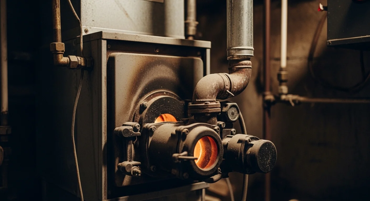
The indoor air quality transformation from oil to heat pump electrification eliminates CO, NOₓ, SO₂, and PM2.5 as heating-related indoor pollutants simultaneously, not sequentially. Occupants in electrified homes measure significantly lower indoor PM2.5 concentrations during heating periods compared to those in combustion-heating households, an improvement with direct cardiovascular and respiratory health implications across all demographics and particularly for children and elderly individuals whose biological vulnerability to air pollution is heightened.
From a systems efficiency perspective, air-source heat pumps operating at a seasonal coefficient of performance (SCOP) of 2.5 to 4.0 deliver between 2.5 and 4.0 units of thermal energy for every unit of electrical energy consumed. This efficiency multiple means that even at current U.S. average electricity carbon intensity, heat pump heating carries a lower lifecycle CO₂ footprint than heating oil combustion in most regions of the country. As the electricity grid decarbonizes further through renewable energy deployment, the climate advantage compounds annually, while the indoor air quality benefit is immediate and absolute from the first day of operation.
The transition pathway for most oil heating households involves replacing the oil furnace or boiler with a ducted or ductless heat pump system, installing supplemental resistance heat for extreme cold design conditions where the heat pump’s rated capacity requires backup, and decommissioning the oil storage tank in accordance with local environmental regulations governing underground and aboveground petroleum storage. The combined public health, environmental, and long-term operational cost benefits of this transition make it the most consequential single action an oil-heated household can take toward improved indoor air quality and permanent elimination of residential CO risk from the heating system.